![]() You don't need to be an 'investor' to invest in Singletrack: 6 days left: 95% of target - Find out more
You don't need to be an 'investor' to invest in Singletrack: 6 days left: 95% of target - Find out more
I bought two 240v ac to 12v dc power converters for a project, but nowhere on the pcb’s does it say 240v in or 12v out.
Can anyone help? They are pretty common as I understand it, but my Google Fu has failed me. 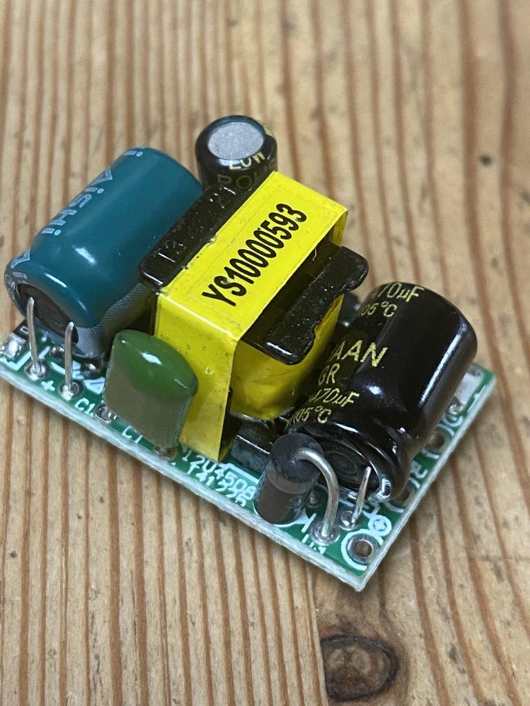
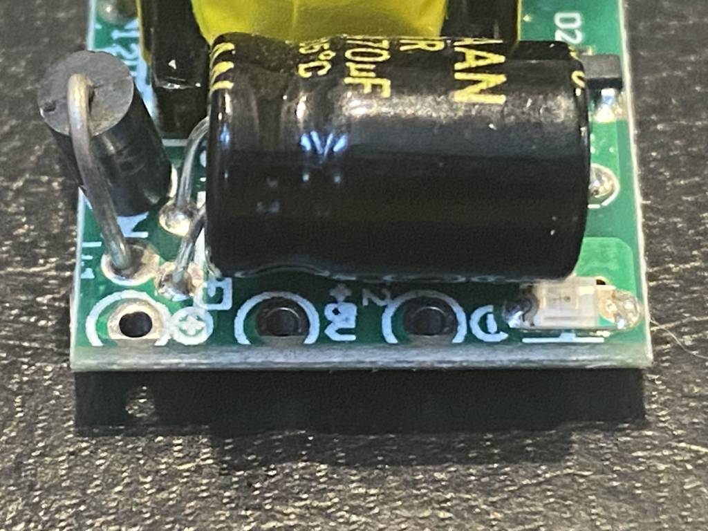
What does it say against each of the three empty holes under the black capacitor? Same question for the two under the blue one?
Is the 3 hole end to allow an earth connection from the 240v in
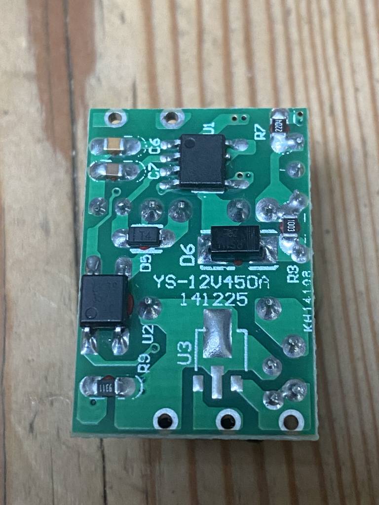
Any writing on the ic's?
Doesn't it say - 5v + on the three holes? That'll be the output then. Anything on the two holes, maybe "~"? Likely to be 240 in

That looks fairly conclusive, but as has been mentioned, it is written on the top side of the PCB. What does it say at the other end?
As requested…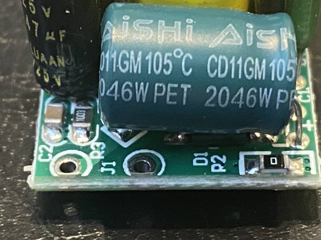
@andyg1966, that is great, what was your search term?
I mainly did not want to damage it by sticking 240v through it the wrong way 😳
Now, where is my stash of excess component legs to put onto these boards?
The + symbol on the PCB is also a indicator of the likely DC end
Out of interest is the middle pin 5V do we think?
Before you use it in anger I would be inclined to dig out the multimeter and measure between the three DC pads to neutral in order to confirm that there is no AC component making it across the board.
Oh absolutely