![]() You don't need to be an 'investor' to invest in Singletrack: 6 days left: 95% of target - Find out more
You don't need to be an 'investor' to invest in Singletrack: 6 days left: 95% of target - Find out more
We had a kitchen fitted last year and at the time we asked the sparky to add in some extra lighting circuits (forward planning as we weren't ready to actually use the new circuits yet).
Anyway, he added a double switch to operate an outside light and low level lighting for a decked area. He installed it and connected up all the live side & earth, leaving the neutral terminated (three wires).
At the same time he also installed all the other lighting in the kitchen, including a two-way switched circuit for all the three banks of lighting in the kitchen/dining area (ie, kitchen lighting, pendant light over table and hanging lights over a bar seating area).
On Saturday I finally got around to fitting an outside light so connected it up outside then wondered where on earth to put the three blue wires in the double switch (as it only has two L2s).
I first tried putting in Blue 1 & 2 in L2 (left) and 3 in L2 (right). I switched on the power and all seemed to be working until I tried the switch and it blew the circuit (tripped the RCD). I then spent half an hour trying different combinations and came to the conclusion that Blue 1 was connected to the pendant light circuit over the table so I terminated that one and tried variations of Blue 1 & 2 in both L2s but then I couldn't get the outside light to come on at all.
So - Blue 1 is clearly needed to make a circuit but it seems to be tripping it when I use it.
I hope this ramble makes sense – I will be getting my normal electrician in (the kitchen fitters subbed their own sparky when the work was done last year) to check it properly (I did actually have him come in and check all the new work and certify it after it was done and he didn't find any issues with any circuits then.
But in the meantime I would appreciate any thoughts/ideas that I could try before having him come in.
Cheers
a sparky will be along to give clear instructions soon but you say blues were terminated - was this the three wires in a terminal block.
If so you probably have a switched live circuit lighting in which case they werent terminated they were just connected as per.
a photo of how it was prior to you fiddling may help .
was this the three wires in a terminal block.
There were three blue wires going into what looked like a professional version of a connector block and the electrician did tell me at the time that he hadn't connected up the circuit.
The block the wires went into looked like this
[img] 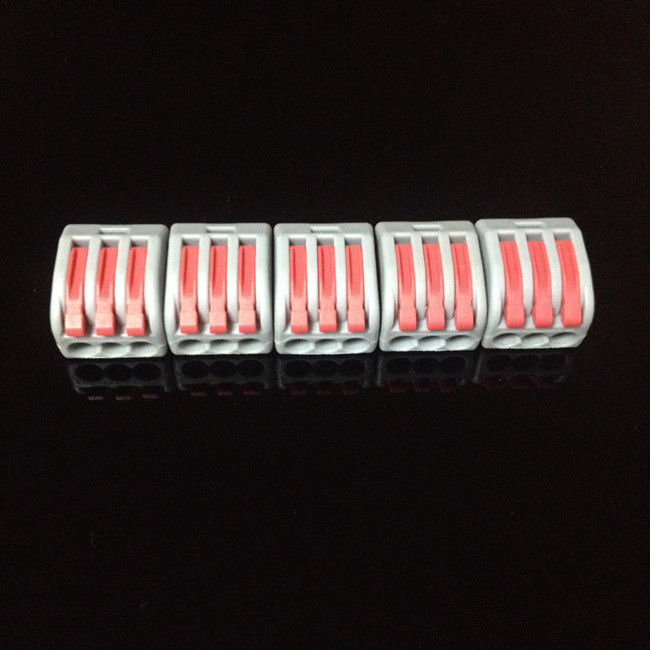 [/img]
But unless i misread -your pendant light worked ....and its neutral was in the terminal block which suggests its not wired up as you think.
That's correct - the pendant light worked and now I have terminated it all again it works again (Blue 1). However if I only use Blue 2 & 3 in the double switch (leaving Blue 1 terminated) the new outside light won't work which is why I am confused.
Well if it worked with the pendant terminated - what makes you think the other two belong in the light switch.
How many live wires are in the switch ?
How many live wires are in the switch ?
Three - it was a new switch fitted by the electrician to operate two new outside lights.
Ok . So there were 3 live wires in the switch and 3 neutrals in the terminal block
And your pendant light worked.....
Which suggests you dont need to have the blue wires in the switch to make it work,
Are you sure the spark didnt mean the switch was wired up and he had terminated it at the light end.....
Light switches are single pole - they only break the live of the circuit. (a double pole switch breaks both live and neutral - generally only used for things like Ovens)
A single switch will usually have 3 terminals (marked L1, L2, and Common) but you only use both L terminals if you have a two switches on the same circuit (eg one by the back door, one by the door to the rest of the house).
So - all the blue wires should be connected together.
But now that I have put it back to how it was (and the pendant light is working as before) the outside light *doesn't* work so the blue wires (at least some of them) need to be connected to the new switch.
(The new switch isn't meant to be part of the other two-way switched circuit, it is meant to simply switch on and off the outside light and low level decking lights).
*ALL* of the brown side is connected up to L1s and common etc it is just the three blue wires that aren't connected up.
I assume he took the feed as a spur from the existing lighting circuit so we have three sets of cable – one coming into the switch (the spur) and two going out (to the outside light and the decking light).
And surely at least two of the blue wires need to be used (one into each of the two L2s) as there needs to be a neutral side to each of the new switched circuits????
Is the live wire to your switch for outside light "live"
Test with multimeter.
And surely at least two of the blue wires need to be used (one into each of the two L2s) as there needs to be a neutral side to each of the new switched circuits???
Please read the link i posted.
If that doesnt make sense please get the spark in. I dont understand why the pendant light works without the blue in the switch and you think that they must go into the switch to make a non working light work
Erm, by terminated do you mean not connected?
If so, please speak to a spark.
I guess I need to get someone in then as this level of understanding is beyond me 🙂
There are a number of ways to skin the cat. Your applying 1 method to the other. Should be easy for a spark to fix up sounds like everything sthere just a case of working out where he has isolated it
I am sure it is simple to someone that knows - I guess I was hoping someone could see the obvious thing I was doing wrong and tell me, thus avoiding the cost of a call out.
Johndoh, can I check I have this right? so you have 3 cables in your double switch box (each cable consists of L,N&E), 1 cable is your feed to the switch, 1 goes to your pendant, 1 goes to your outside light?
Put all three neutrals (blues) together in the Wago connector (the fancy looking connector pictured above)
Assuming you have your switch for the pendant light terminated as before, it should now work.
If your pendant is working now and you can switch it on/off properly,that means you should have your feed into the switch at the common, C, terminal and the switch line for the pendant coming out of L1. If you have a multimeter or voltstick, verify this. With the light switch turned off, you should have voltage at terminal C
You should have a short loop of brown from the common, C, of the pendant light to the common terminal of switch for the outside light. For your outside light, connect the switch line (brown core) into the other L1 terminal.
Good luck!
1 cable is your feed to the switch, 1 goes to your pendant, 1 goes to your outside light?
Not quite - there *should* be two feeds to the outside (one to the outside light, one to low level lighting (not yet installed.
The double switch should operate both of the outside lights but *not* the indoor pendant.
That make sense?
I need to see a photo inside the double switch to be able to advise on this one.
Rich (electrician)
I shall try to do that tonight then - cheers
Right here goes...
[img] 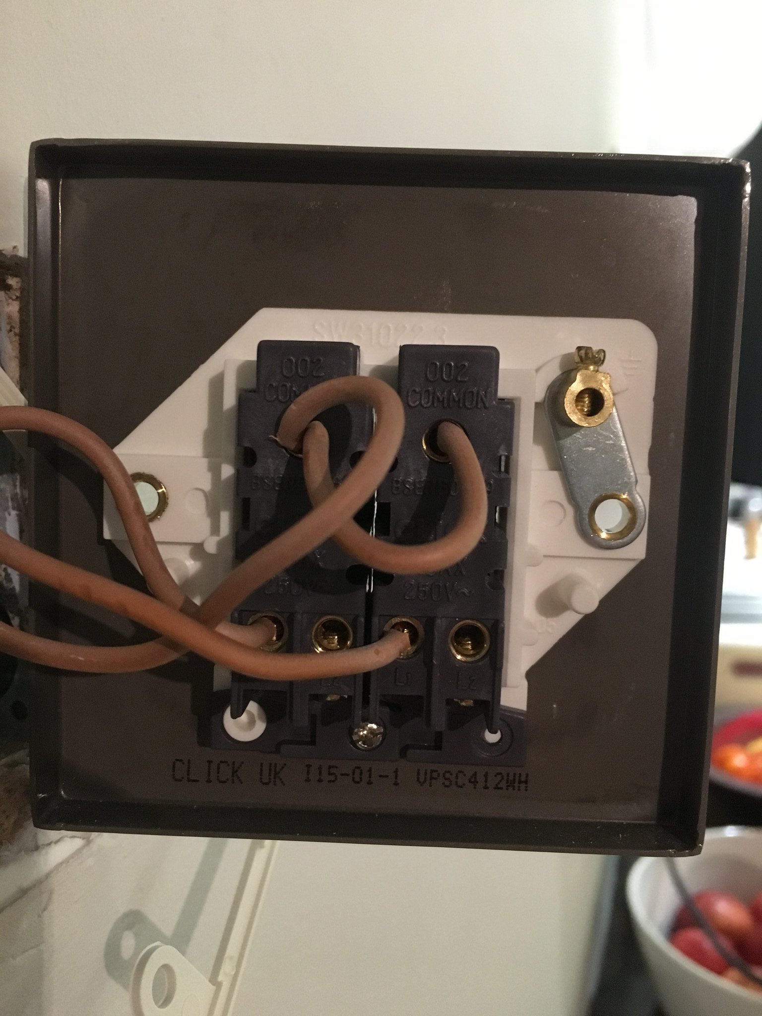 [/img]
[img] 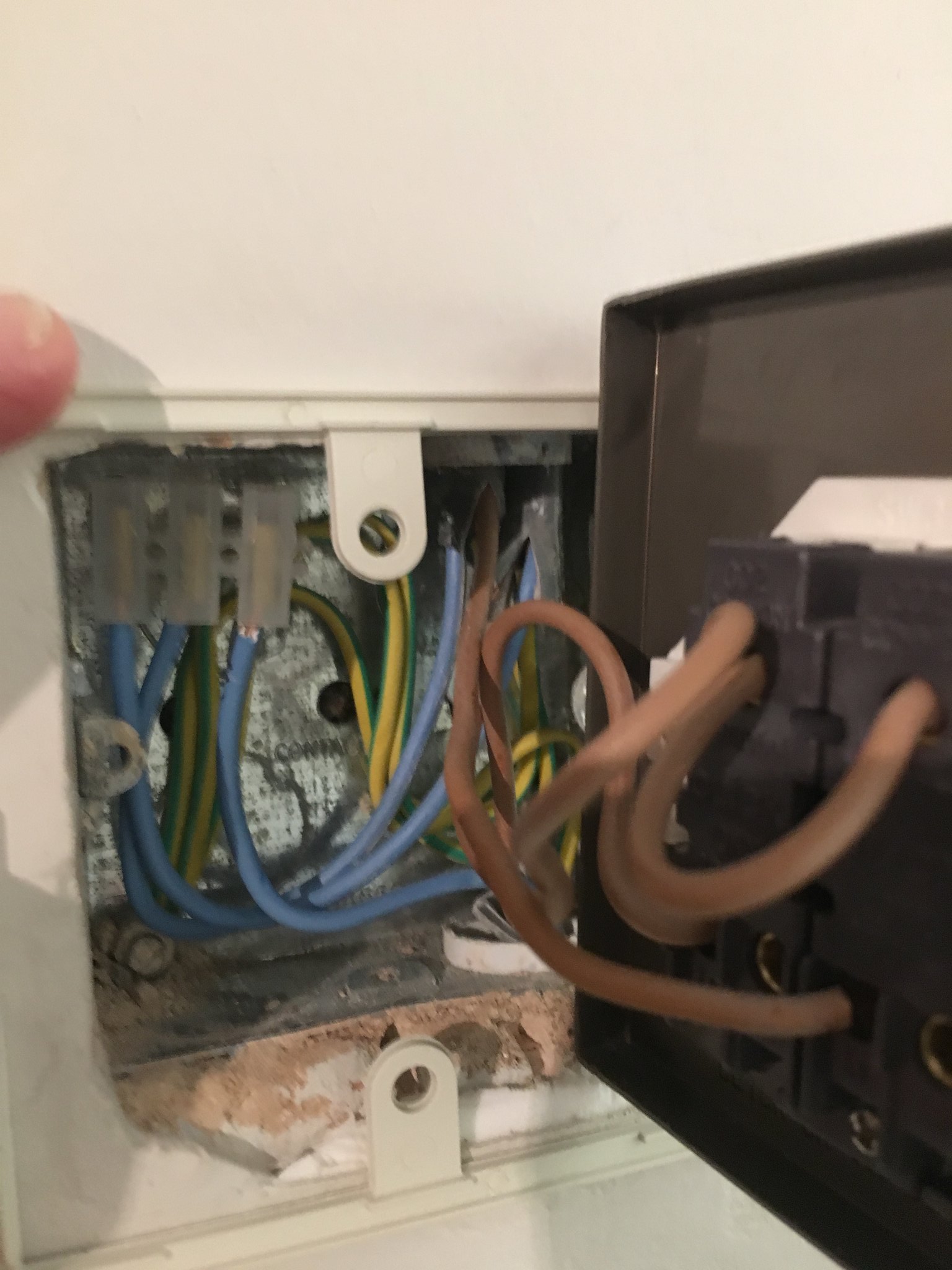 [/img]
[img] 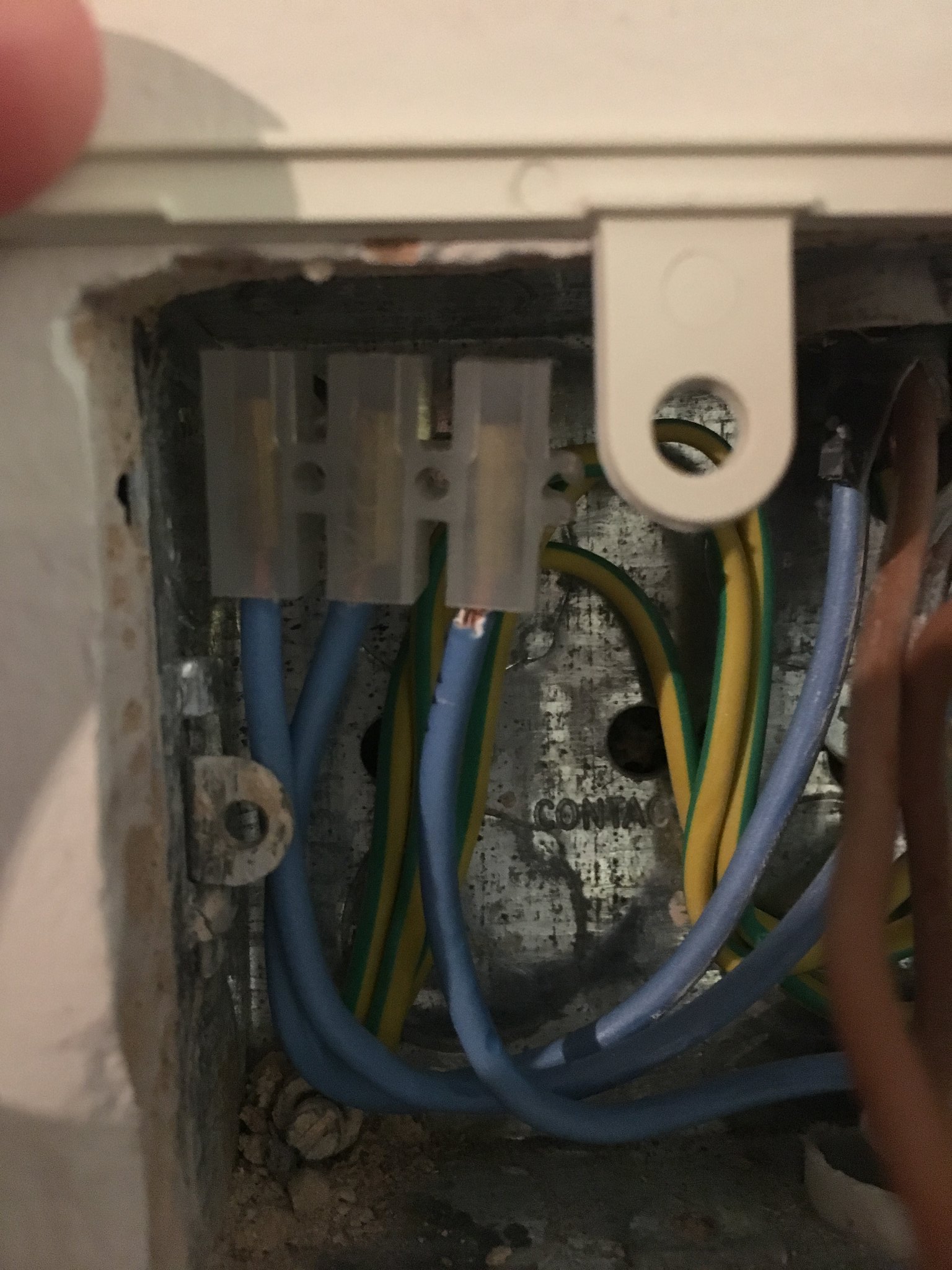 [/img]
So your feed, loop and switch lines look okay from here. Do you have a voltage tester to check if you have 240V at the common terminal. I would have thought that your 3 neutrals should be together.
Ok. That all looks ok to me.
Picture 1:
Live in is going to the top left (commmon) connector on the switch. This is then bridged over to the common on the other, right hand connector. The two bottom browns are both switched lives.
Picture 2:
Blues are all neutrals. These are properly terminated.
Picture 3:
Earths look good too - terminated in the earthihng point of the back box.
(Nice job, but not as tidy as mine :wink:)
What might of happened is that he's made all the correct connections but has not made the live connection at the point where he's taken the live feed. You need to find out where this is - maybe the ceiling rose or more probably the switch for the kitchen area and see if there is a spare live unconnected in there.
Start with that and report back! Any questions, just ask.
Rich.
No I don't have a tester, all I have is one of those voltage pens so a bit basic (it'd pick up voltage from nearby wire I think.
And what do you mean by the neutrals being together? As in they should all be connected up in the same loop?
I assume that wouldn't be on either of the L2s - just connected to each other???
I would have thought that your 3 neutrals should be together
Good spot! These should be linked together.
I still think the live is not connected though.
Looking at those photos.
If the pendant is working and the commons connected between them ....Surely the live is hooked up ?
Pretty sure there are no further unconnected terminals at the ceiling rose as I wired up a new light on that recently (7pm on Christmas Eve to be precise) 🙂
Hth
[URL= http://i884.photobucket.com/albums/ac50/tymbian/Mobile%20Uploads/2016-12/FB_IMG_1482956973924_zpsgu0wgmwb.jp g" target="_blank"> http://i884.photobucket.com/albums/ac50/tymbian/Mobile%20Uploads/2016-12/FB_IMG_1482956973924_zpsgu0wgmwb.jp g"/> [/IMG][/URL]
And there is a live connection as I could make the new light come on (although tripping on switch) when I put all three neutrals into the L2s...
The blues are not connected to anything ? Hows that working ?
No I don't have a tester, all I have is one of those voltage pens so a bit basic (it'd pick up voltage from nearby wire I think.And what do you mean by the neutrals being together? As in they should all be connected up in the same loop?
I assume that wouldn't be on either of the L2s - just connected to each other???
some voltsticks are good, some bad. Try it though, at the common terminal where the loop is. all we want to do is prove you have 240V at the feed.
Don't put anything into L2, that's for 2 way switching.
Put your neutrals all into 1 connector. Oh and have a headlamp to hand, just incase!
That, Trail Rat, is what continues to confound me...
What spectraken said
When you described in a block earlier I thought you meant together. You shouldn't really have any lights the ground circuits broken on all counts right noe isn't it
Johndoh, if you still have the orange grey lever wago connector, put all 3 neutrals in there. otherwise use the plastic terminal block and put all three into 1 screw termination and with a little bit of luck you might have some lights!
That, Trail Rat, is what continues to confound me...
The blues, once put together will form the continuous neutral path. One of them is the neutral from the main consumer unit (via other fittings). The other two are the neutrals that go to a) the outside light and b) the patio light (assuming we've understood things correctly).
If they are not together the circuit will not be complete and nothing will work.
What spectraken is trying to establish is whether there the switch has power to it or not. If so, then the outside light that has been fitted should operate. If not, then we need to establish why no power is there - probably because the connection hasn't been made.
My guess is this is the case as it would be poor practice to make the live connection to fixtures that have yet to be installed. Neutrals disconnected would not stop voltage being present at the fixture if the switch was turned on and consequently you could get a shock.
The installation looks neat and tidy and my experience is that anyone doing a neat job is not likely then to short cut the safety bit. (I'll be proved wrong now!).
Thank you! Connected them together and all is working as it should.
Very much appreciated:-)